 Click here for a PDF of the Fire Alarm Interface Cable (FAIC4M) Connection Manual, V1.1.
This guide shows how to connect a Sensar Marine Expansion Hub (EH700) to a smoke alarm or fire detection system using the Sensar Marine Fire Alarm Interface Cable (FAIC4M).
Please note: the interface cable has two output wires in one end which connects to the Expansion Hub and four input wires in the other end which connects to the external detection system.
Towards Expansion Hub
Two wires:
- Red: Splice to the White wire ("Fire Alarm Positive") on cable marked "Expansion 1"
- Black: Splice to the Green wire ("Fire Alarm Negative") on cable marked "Expansion 1"

Towards Fire Alarm System
Note! The interface cable inputs are rated for 0 - 36 V. The expected input voltages are 10 - 36 V. The Fire Alarm Interface Cable does not provide an output reference voltage for the inputs. All input voltages must be sourced externally, preferably from the alarm system.
Four wires:
- Black = GND
- Red = Active. Connect to the same power that supplies the detection system.
- Orange = Alarm. Should only be energized when there is an alarm.
- Yellow = Fault. Should only be energized when there is a system fault.
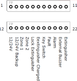
Example - FireBoy FBD-2 Fire Alarm Panel
- Red = Pin 12 "12/24V"
- Yellow = Pin 8 "Fault"
- Orange = Pin 9 "Alarm"
- Sourcing voltage for inputs from alarm system:
- Black = Pin 1 "Ground"
- Short Pin 12, "12/24V" to Pin 19 "Fault", Pin 20 "Alarm"
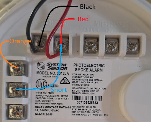
Example - Fire-Lite (2012JA) Smoke Detector with Form C Alarm Relay
- Connect "Power input+" to "C". Ensures smoke detector signals using its supply voltage.
- Black (GND): Connect to "Power Input -"
- Red (Active): Connect to "Power input+"
- Orange (Alarm): Connect to "NO"
- Yellow (Fault): Secure and stow, since there is no fault indicator on 2012JA
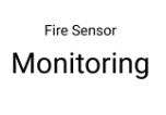
Testing Alarm
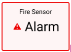
Most alarm systems have a delay to avoid false alarms. The Expansion Hub will begin the alert process after ~6 seconds of signalled alarm, upon which it will connect to cellular and send SMS and data to the app. The Fire Alarm tile in the app should turn red and say "Alarm".
The time spent connecting and sending SMS depends on local conditions such as cellular coverage, but is typically done within 25-35 seconds.
Testing Active
The Expansion Hub will also raise an alarm ~6 seconds after the fire alarm power is lost, i.e. the Active cable (Red) loses voltage.